Figuring Out VCF Automation 9
I’ll be honest, I haven’t been a heavy VCF Automation user, and I’ve never fully explored everything the platform can do. That’s something I wanted to change. As I started digging deeper into VCF Automation 9, I quickly realized that understanding all the concepts and how they fit together isn’t always straightforward.
This article is my attempt to break down those concepts and explain how they connect. It is not a deployment guide, instead the focus is on understanding the platform architecture and how you can design your environment using the different building blocks available.
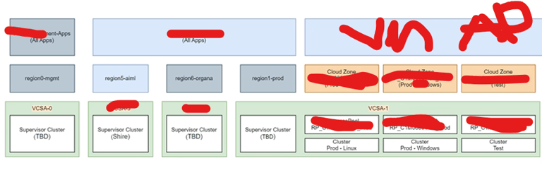
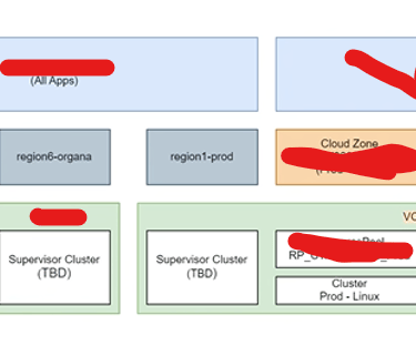
One of the major changes introduced in VCF Automation 9 is the distinction between All Apps and the more traditional VM Apps experience.
VM Apps focuses on virtual machine–based deployments and is designed for teams working primarily with traditional infrastructure services.
All Apps expands the scope to include virtual machines, Kubernetes workloads, and modern application deployments within a unified model.
Why are there two models?
Different teams have different ways of working:
Some infrastructure teams mainly operate VM services and classic provisioning workflows. For them, VM Apps provides a simpler and more familiar experience.
Developers and platform teams often work with namespaces, YAML-based definitions, and cloud-native tooling. In these scenarios, All Apps offers a more flexible and modern development platform.
In this article, we will focus on the All Apps model and explore how it can be used to design a flexible and scalable platform with VCF Automation.
POSTED XXX XXX


VCF Automation – Initial Configuration Overview
After deploying VCF Automation, you are guided through a Get Started workflow that helps you prepare the platform before deploying workloads.
These first configuration steps are important because they define:
where workloads can run
how networking is structured
and how tenant boundaries are separated
Think of this phase as building the foundation layer of your automation platform.
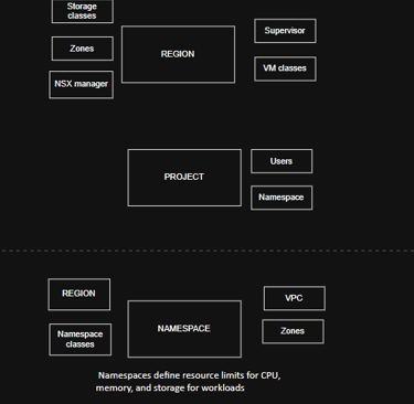
Region
A Region defines where workloads can be deployed from an infrastructure perspective.
It represents the logical scope of compute, storage, and networking that Automation exposes to tenants.
In many environments, a Region maps to something familiar, such as:
a Workload Domain
a Datacenter
a geographical site
or another logical infrastructure boundary
When creating a Region, you connect it to a single NSX Manager, which becomes the networking control plane for that Region.
During setup, you also select:
Supervisor clusters — where workloads actually run
Storage Classes — used for persistent storage provisioning
This allows Automation to understand both the networking and storage capabilities available before anything is deployed.
👉 Simple explanation:
A Region is basically “this is the infrastructure area where workloads are allowed to live.”
Organization
Next, you create an Organization.
An Organization is the top-level tenant boundary in VCF Automation.
It is used to separate teams, departments, or customers while still maintaining centralized control from the platform team.
Inside an Organization, administrators can define quotas that control how much infrastructure can be used, for example:
which Regions are available
which Supervisors workloads can run on
placement Zones and availability limits
This allows platform teams to enforce governance while still giving tenants flexibility.
Important relationship:
✅ Organization owns Projects
❌ Organization does not directly own Namespaces
👉 Simple explanation:
An Organization is who owns and consumes the platform.
IP Space
An IP Space acts as centralized IP Address Management inside VCF Automation.
Instead of every tenant creating their own IP ranges, IP Spaces define structured pools of addresses that can be safely reused across Regions and Organizations without overlap.
IP Spaces are used for:
NAT and external connectivity
Load Balancer virtual IPs
Floating IP assignments
👉 Simple explanation:
IP Space = the master pool of IP addresses the platform hands out.
Provider Gateway
A Provider Gateway connects Organizations to external networks.
It is backed by an NSX Tier-0 Gateway (or Tier-0 VRF) and provides north-south routing using IP ranges from IP Spaces.
Provider Gateways are owned by the platform team and can be shared between multiple Organizations.
👉 Simple explanation:
Provider Gateway = the shared exit point to the outside network.
Regional Network Settings
Regional Network Settings control which networking resources an Organization is allowed to use inside a Region.
They don’t create networking components — they simply expose approved platform resources such as:
Provider Gateways
IP Spaces
predefined networking options
This keeps the platform controlled while still allowing tenants to deploy workloads easily.
👉 Simple explanation:
This step decides which networking tools each Organization is allowed to see.
Project and Workload Components Overview
After the platform foundation is in place, the next step is defining how users actually consume resources.
This is where Projects, Namespaces, and networking constructs like VPCs come together to form the workload layer.
Project
A Project is the main working space inside an Organization.
It connects users, infrastructure, and policies, and defines where workloads can be deployed.
A Project typically includes:
Users — who is allowed to deploy and manage workloads
Namespaces — where workloads actually run
Regions and Zones — which infrastructure locations are available
👉 Simple explanation:
A Project is the workspace where teams deploy applications.
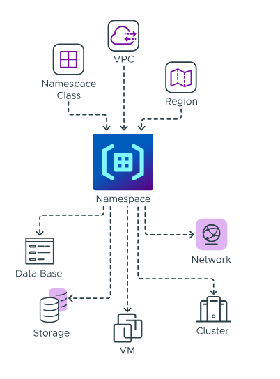
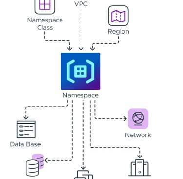
Namespaces
Namespaces live in the vSphere Supervisor layer and define resource boundaries for workloads like virtual machines and Kubernetes clusters.
A Namespace includes:
Namespace Class – defines the template and policies for the Namespace
Region – determines the infrastructure location where workloads are deployed
VPC – provides the networking environment for workloads
Namespaces are not owned by Organizations directly.
Instead, they are connected to Projects inside Automation.
Key relationships:
✅ Namespace lives in vSphere Supervisor
✅ Project consumes Namespace through Automation
👉 Simple explanation:
Namespace = the actual runtime space where workloads execute.
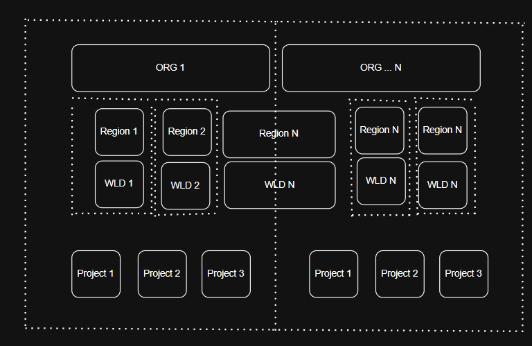
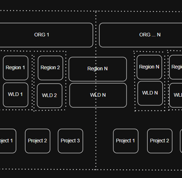
Now that we’ve covered the core components you need to configure, let’s look at how everything fits together visually.
A VPC is defined by the components that control where it exists and how it connects externally:
Region – determines the infrastructure location of the VPC
Connectivity Profile – defines shared northbound connectivity and external routing settings
👉 Simple explanation:
VPC = the private network environment for your workloads.
Summary
Organization → who has access
Region → which infrastructure is offered
Project → where workloads are deployed
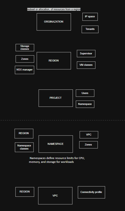
This is not a prescriptive design for a VCF Automation platform, but rather an example meant to inspire how you might structure your own environment. Below is a diagram showing the full picture:
VirtualViking
Plundering the Old Ways, Automating the New!
Tech
© 2024. All rights reserved.